
SAR data
Contents
SAR data
Implemented SAR satellites
Satellites |
Class |
Product Types |
Use archive |
|---|---|---|---|
Sentinel-1 |
SLC & GRD |
Yes |
|
COSMO-Skymed 1st Generation |
DGM & SCS, (others should also be OK) |
No |
|
COSMO-Skymed 2nd Generation |
DGM & SCS, (others should also be OK) |
No |
|
TerraSAR-X & TanDEM-X & PAZ SAR |
MGD (SSC should be OK) |
No |
|
RADARSAT-2 |
SGF (SLC should be OK) |
Yes |
|
RADARSAT-Constellation |
GRD (others should be OK) |
No |
|
ICEYE |
GRD (SLC not used) |
No |
Warning
Satellites products that cannot be used as archived have to be extracted before use, mostly because SNAP doesn’t handle them.
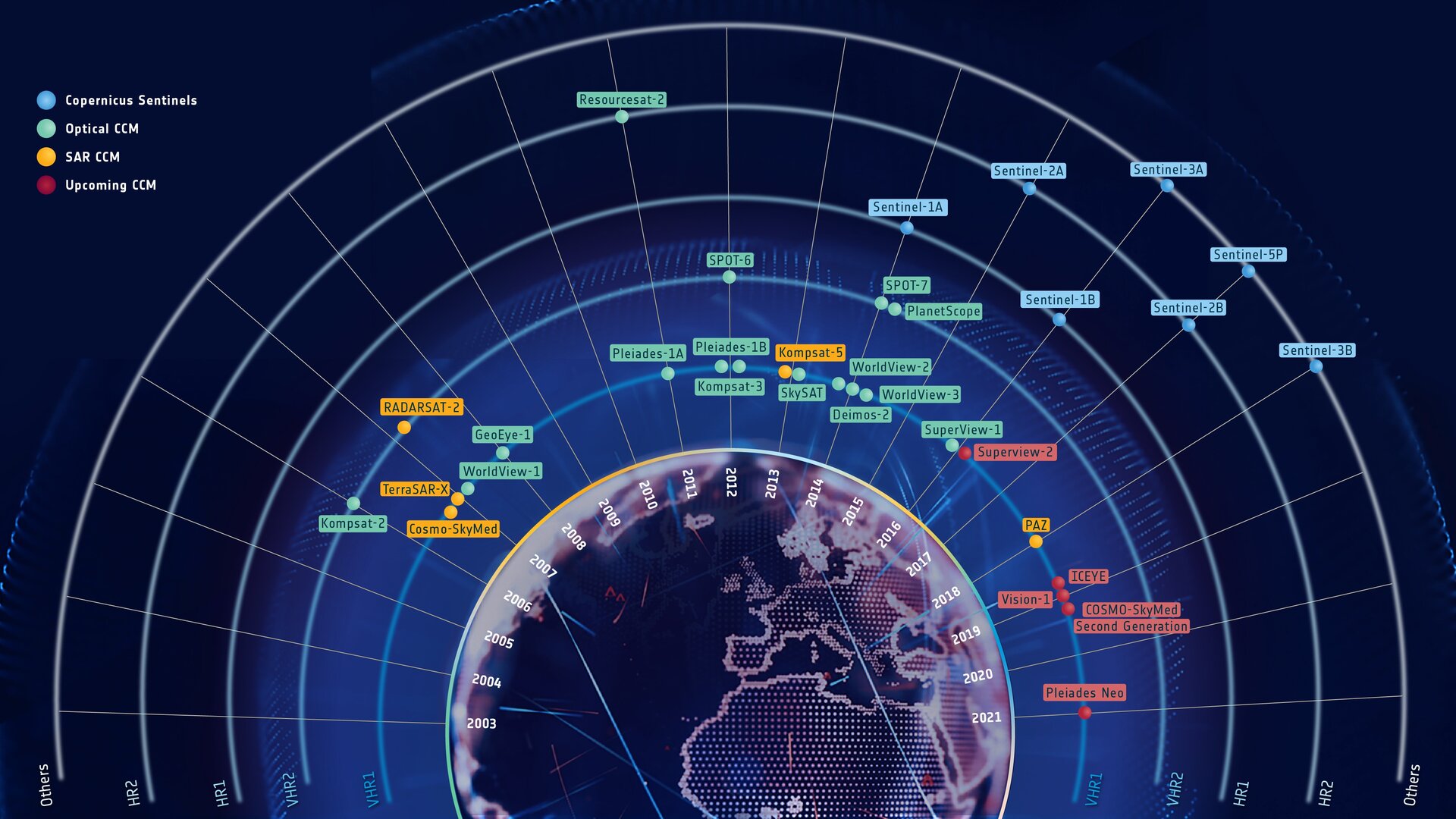
The goal of EOReader is to implement every sensor that can be used in
the Copernicus Emergency Management Service.
The sensors that can be used during CEMS activations are (as of 09/2021):
SAR Bands
Warning
EOReader always loads SAR bands in a GRD format. This library is not (yet ?) meant to manage inSAR or other complex processes.
According to what contains the products, allowed SAR bands are:
You also can load despeckled bands:
DEM bands
These bands need a valid worldwide DEM path positioned thanks to the environment variable EOREADER_SAR_DEFAULT_RES
DEMSLOPE
SAR satellites can only load DEM and SLOPE
bands as the sun position does not impact SAR data. The SLOPE band is given in degrees. Please post an issue if you
need this band in percent.
These bands need a valid worldwide DEM path positioned thanks to the environment variable EOREADER_DEM_PATH.
You can use both a local path e.g. /mnt/dataserver/dems/srtm_30_v4/index.vrt or \\dataserver\DEMS\srtm_30_v4\index.vrt or
a URL pointing to a web resources hosted on a S3 compatible storage e.g.
https://s3.storage.com/dem-bucket/srtm_cog.tif (not available on Windows for now).
Default resolution
The default resolution of SAR products depends on their type. Complex data are always converted back to ground range to be used, so the complex resolution is never used by EOReader.
The product resolution is read in the metadata file if possible, except for complex data. For them, Grand Range values from the constructor are used.
Sentinel-1
Sentinel-1 |
Single Look Complex (SLC) |
Ground Range Detected (GRD) |
Ground Range Detected (GRD) |
Ground Range Detected (GRD) |
|---|---|---|---|---|
StripMap (SM) |
1.5x3.6 m to 3.1x4.1 m |
3.5m |
10.0m |
40.0m |
Interferometric Wide swath (IW) |
2.3x14.1 m |
10.0m |
40.0m |
|
Extra-Wide swath (EW) |
5.9x19.9 m |
25.0m |
40.0m |
|
Wave (WV) |
1.7x4.1 m and 2.7x4.1 m |
25.0m |
COSMO-Skymed 1st Generation
COSMO-Skymed 1st Generation |
Single-look Complex Slant (SCS) |
Detected Ground Multi-look (DGM) |
|---|---|---|
Spotlight |
1.1-0.9x0.91m |
1.0m |
StripMap |
3.0-2.6x2.4-2.6m |
5.0m |
StripMap |
11-10x9.7m |
20.0m |
ScanSAR |
13.5x23m |
30.0m |
ScanSAR |
13.5x38.0m |
100.0m |
COSMO-Skymed 2nd Generation
Only for Standard products
COSMO-Skymed 2nd Generation |
Single-look Complex Slant (SCS) |
Detected Ground Multi-look (DGM)Geocoded Ellipsoid Corrected (GEC) |
|---|---|---|
SPOTLIGHT_2_A |
~0.25m |
#1: 0.15m (apodized: 0.12m) |
SPOTLIGHT_2_B |
~0.45m |
#1: 0.25m (apodized: 0.2m) |
SPOTLIGHT-2C |
~0.56m |
#1: 0.30m (apodized: 0.24m) |
STRIPMAP & QUADPOL |
≤ 3.0m |
#1: 1.25m |
SCANSAR1 |
14.0m |
#1: 5.0m |
SCANSAR2 |
27.0m |
#1: 10.0m |
PINGPONG |
8.0m |
#1: 2.0m |
#1, #2 and #3 correspond to the MultiLook ID.
TerraSAR-X & TanDEM-X & PAZ SAR
TerraSAR-X & TanDEM-X & PAZ SAR |
Single-look Slant Range (SSC) |
Multi Look Ground Range (MGD) |
Multi Look Ground Range (MGD) |
|---|---|---|---|
StripMap (SM) |
0.9x2.0m |
1.5m or 1.25m |
4.0m or 3.25m |
StripMap (SM) |
0.9x2.5m |
3.0m |
5.5m or 4.5m |
High Resolution Spotlight (HS) |
0.9x0.8m |
1.5m or 0.5m |
2.0m or 1.5m |
High Resolution Spotlight (HS) |
0.9x1.5m |
1.5m or 1.0m |
3.0m or 2.0m |
Spotlight (SL) |
0.9x1.3m |
1.5m or 0.75m |
3.0m or 1.75m |
Spotlight (SL) |
0.9x2.6m |
3.5m or 3.4m |
8.5m or 5.5m |
Staring Spotlight (ST) |
0.5x0.2m |
0.4m or 0.2m |
0.8m or 0.4m |
ScanSAR (SC) |
0.9x13m |
8.25m |
|
ScanSAR (SC) |
1.4x?m |
15.0m |
RADARSAT-2
RADARSAT-2 |
Single-look complex (SLC) |
SAR georeferenced extra(SGX) |
SAR georeferenced fine (SGF) |
SAR systematic geocorrected (SSG) |
SAR precision geocorrected (SPG) |
ScanSAR narrow beam (SCN) |
ScanSAR wide beam (SCW) |
ScanSAR fine (SCF) |
ScanSAR sampled (SCS) |
|---|---|---|---|---|---|---|---|---|---|
Spotlight |
1.3x0.4m |
1.0 or 0.8x1/3m |
0.5m |
0.5m |
0.5m |
||||
Ultra-Fine |
1.3x2.1m |
1.0x1.0 or 0.8x0.8m |
1.56m |
1.56m |
1.56m |
||||
Wide Ultra-Fine |
1.3x2.1m |
1.0m |
1.56m |
1.56m |
1.56m |
||||
Multi-Look Fine |
2.7x2.9m |
3.13m |
6.25m |
6.25m |
6.25m |
||||
Wide Multi-Look Fine |
2.7x2.9m |
3.13m |
6.25m |
6.25m |
6.25m |
||||
Extra-Fine |
Full Res: 2.7x2.9m |
1 look: 2.0m |
1 look: 3.13m |
3.13m |
3.13m |
||||
Fine |
4.7x5.1m |
3.13m |
6.25m |
6.25m |
6.25m |
||||
Wide-Fine |
4.7x5.1m |
3.13m |
6.25m |
6.25m |
6.25m |
||||
Standard |
8.0 or 11.8x5.1m |
8.0m |
12.5m |
12.5m |
12.5m |
||||
Wide |
11.8x5.1m |
10.0m |
12.5m |
12.5m |
12.5m |
||||
Extended High |
11.8x5.1m |
8.0m |
12.5m |
12.5m |
12.5m |
||||
Extended Low |
8.0x5.1m |
10.0m |
12.5m |
12.5m |
12.5m |
||||
Fine Quad-Pol |
4.7x5.1m |
3.13m |
3.13m |
3.13m |
3.13m |
||||
Wide Quad-Pol |
4.7x5.1m |
3.13m |
3.13m |
3.13m |
3.13m |
||||
Standard Quad-Pol |
8.0 or 11.8x5.1m |
8.0x3.13m |
8.0x3.13m |
8.0x3.13m |
8.0x3.13m |
||||
Wide Standard Quad-Pol |
8.0 or 11.8x5.1m |
8.0x3.13m |
8.0x3.13m |
8.0x3.13m |
8.0x3.13m |
||||
ScanSAR Narrow |
25.0m |
25.0m |
25.0m |
||||||
ScanSAR Wide |
50.0m |
50.0m |
50.0m |
||||||
Ship (Detection of vessels) |
40.0m |
20.0m |
|||||||
Ocean Surveillance |
50.0m |
35.0x25.0m |
RADARSAT-Constellation
RADARSAT-Constellation |
Resolution* |
|---|---|
Spotlight [FSL] |
≈ 1.0 x 3.0m à 35° |
Very-High Resolution, 3 meters [3M] |
≈ 3.0 x 3.0m à 35° |
High Resolution, 5 meters [5M] |
≈ 5.0 x 5.0m |
Quad-Polarization [QP] |
≈ 9.0 x 9.0m |
Medium Resolution, 16 meters [16M] |
≈ 16.0 x 16.0m |
Medium Resolution, 30 meters [SC30] |
≈ 30.0 x 30.0m |
Medium Resolution, 50 meters [SC50] |
≈ 50.0 x 50.0m |
Low Noise [SCLN] |
≈ 100.0 x 100.0m |
Low Resolution, 100 meters [SC100] |
≈ 100.0 x 100.0m |
Ship Detection |
Variable |
* Same resolution for every product type according to that page.
ICEYE
For GRD products:
ICEYE |
Ground sample spacing (pixel size) |
|---|---|
Spotlight [SL(H)] |
0.5m |
StripMap [SM(H)] |
2.5m |
Scan [SC] |
6.0m |
ICEYE |
Resolution |
|---|---|
Spotlight [SL(H)] |
1.0m |
StripMap [SM(H)] |
3.0m |
Scan [SC] |
< 15.0m |
GPT graphs
You can change the SAR GPT graphs used by setting the following environment variables:
EOREADER_PP_GRAPH: Environment variables for pre-processing graph path.EOREADER_DSPK_GRAPH: Environment variables for despeckling graph path
Warning
For performance reasons, the Terrain Correction step is done before the Despeckle step. Indeed this step is very
time-consuming and better done one time on the raw image than two times on both the raw and the despeckled image. Even
if this is not the regular way of handling SAR data, this shouldn’t really affect the quality of any extraction done
after that.
You can change the DEM used for the Terrain Correction step by positioning the EOREADER_SNAP_DEM_NAME environment variable.
Available DEMs are:
ACE2_5MinACE30ASTER 1sec GDEMCopernicus 30m Global DEM(buggy for now, do not use it)Copernicus 90m Global DEM(buggy for now, do not use it)GETASSE30(by default)SRTM 1Sec HGTSRTM 3SecExternal DEM
If External DEM is set, you must specify the DEM you want by positioning the EOREADER_DEM_PATH to a DEM that can be read by SNAP.
What to know if you are changing a graph
Those graphs should have a reader and a writer on this model:
<graph id="Graph">
 <version>1.0</version>
 <node id="Read">
  <operator>Read</operator>
  <sources/>
  <parameters class="com.bc.ceres.binding.dom.XppDomElement">
  <file>$file</file>
  </parameters>
 </node>
 <node id="Write">
  <operator>Write</operator>
  <sources>
  <sourceProduct refid="????"/>
  </sources>
  <parameters class="com.bc.ceres.binding.dom.XppDomElement">
  <file>$out</file>
  <formatName>BEAM-DIMAP</formatName>
  </parameters>
 </node>
</graph>
Warning
Pay attention to set $file and $out and leave the BEAM-DIMAP file format. The first graph must orthorectify your
SAR data, but should not despeckle it. The second graph is precisely charged to do it.
The pre-processing graph should also have a Terrain Correction step with the following wildcards that are set automatically in the module:
$res_m: Resolution in meters$res_deg: Resolution in degrees$crs: CRSThe nodata value should always be set to 0.
The default Terrain Correction step is:
<node id="Terrain-Correction">
 <operator>Terrain-Correction</operator>
 <sources>
  <sourceProduct refid="LinearToFromdB"/>
 </sources>
 <parameters class="com.bc.ceres.binding.dom.XppDomElement">
  <sourceBands/>
  <demName>GETASSE30</demName>
  <externalDEMFile/>
  <externalDEMNoDataValue>0.0</externalDEMNoDataValue>
  <externalDEMApplyEGM>true</externalDEMApplyEGM>
  <demResamplingMethod>BILINEAR_INTERPOLATION</demResamplingMethod>
  <imgResamplingMethod>BILINEAR_INTERPOLATION</imgResamplingMethod>
  <pixelSpacingInMeter>$res_m</pixelSpacingInMeter>
  <pixelSpacingInDegree>$res_deg</pixelSpacingInDegree>
  <mapProjection>$crs</mapProjection>
  <alignToStandardGrid>false</alignToStandardGrid>
  <standardGridOriginX>0.0</standardGridOriginX>
  <standardGridOriginY>0.0</standardGridOriginY>
  <nodataValueAtSea>true</nodataValueAtSea>
  <saveDEM>false</saveDEM>
  <saveLatLon>false</saveLatLon>
  <saveIncidenceAngleFromEllipsoid>false</saveIncidenceAngleFromEllipsoid>
  <saveLocalIncidenceAngle>false</saveLocalIncidenceAngle>
  <saveProjectedLocalIncidenceAngle>false</saveProjectedLocalIncidenceAngle>
  <saveSelectedSourceBand>true</saveSelectedSourceBand>
  <outputComplex>false</outputComplex>
  <applyRadiometricNormalization>false</applyRadiometricNormalization>
  <saveSigmaNought>false</saveSigmaNought>
  <saveGammaNought>false</saveGammaNought>
  <saveBetaNought>false</saveBetaNought>
  <incidenceAngleForSigma0>Use projected local incidence angle from DEM</incidenceAngleForSigma0>
  <incidenceAngleForGamma0>Use projected local incidence angle from DEM</incidenceAngleForGamma0>
  <auxFile>Latest Auxiliary File</auxFile>
  <externalAuxFile/>
 </parameters>
</node>
Default SNAP resolution
You can override default SNAP resolution (in meters) when geocoding SAR bands by setting the following environment variable:
EOREADER_SAR_DEFAULT_RES(0.0 by default, which means using the product’s default resolution)